Category: reaction mechanism

  • Mechanism of reaction between titanocene pentasulfide and sulfenyl chloride: The effect of continuum solvation on the energy surface.

    An investigation of the kinetics of the reaction between titanocene pentasulfide and sulfenyl chloride[cite]10.1039/d4sc02737j[/cite] leading to the formation of the S7 allotrope of sulfur was accompanied by supporting DFT calculations which led to the conclusion that of five possible mechanisms for the reaction, the most probable corresponded to a variant of the concerted σ-bond metathesis (Scheme 1, Mechanism IV, R = Cl). Here we take a closer look at the DFT predictions from the point of view of the impact of continuum solvation on the calculated mechanism.

    Scheme 1.  Possible reaction mechanisms.

    The original study used the new r2scan-3c/Def2-mTZVPP composite DFT functional[cite]10.1063/5.0040021[/cite] as implemented in the ORCA 6 program code,[cite]10.1063/5.0004608[/cite] for which the (gas phase) mechanistic reported pathway was obtained as shown in scheme 2 below. Here, we re-label the succeeding steps as TS3 and TS4 (see Scheme 3 below, rather than TS2 from scheme 2) to form the final product P, for reasons that will become apparent below.

    Scheme 2.  Reaction  scheme and energy profile.[cite]10.1039/d4sc02737j[/cite]

    Methodology

    In this study, we used an older functional, MN15L[cite]10.1021/acs.jctc.5b01082[/cite] for R=Cl (scheme 1), which we have found very effective for the transition elements[cite]10.1002/adsc.202400909[/cite] and which – like r2scan-3c – was designed to be accurate for multi-reference and single-reference systems and for noncovalent interactions, This functional, unlike r2scan-3c, is implemented in the Gaussian 16 program code and hence has the advantage of allowing computed intrinsic reaction coordinate (IRC) data to be usefully visualised using e.g. Gaussview.‡ Transition state geometries were initially obtained from the supporting information given in the original article [cite]10.1039/d4sc02737j[/cite] and re-optimised in the Gaussian program using MN15L/Def2-TZVPP. The thermochemical energies shown in Table A1 were all obtained using GoodVibes[cite]10.5281/zenodo.1435820[/cite] (see manual) with an entropic quasi-harmonic treatment frequency cut-off value of 2.0 wavenumbers[cite]10.1002/chem.201200497[/cite] and an enthalpic quasi-harmonic treatment frequency cut-off value of 50.0 wavenumbers.[cite]10.1021/jp509921r[/cite] In the table, harmonic values are indicated as e.g. hG and quasi-harmonic values as qh-G; the difference between these two is relative small. If desired, other harmonic cut-off values can be obtained, as well as at other molar concentrations, using log files obtained from the repository DOIs indicated below, via the command line:

    python3 -m goodvibes -q --fs 2 --fh 50 -c 0.0409 logfilename.

    Results

    Part 1: Gas phase model

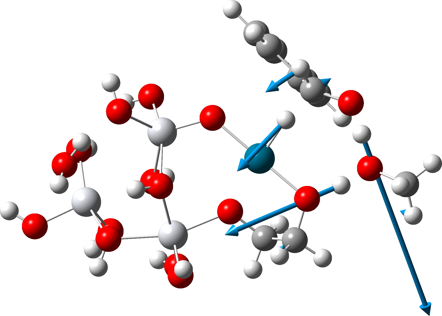
    The intrinsic reaction coordinate (IRC) deriving from transition state TS1 computed using Gaussian 16, and without inclusion of a solvent continuum model (a gas phase model) is shown below (Table 1, Figure 1).[cite]10.14469/hpc/15219[/cite] It leads directly to the “half-way” product Int2, with no intervening intermediate such as that shown in Scheme 2 (there labelled Int1[cite]10.1039/d4sc02737j[/cite]). So here, the TS1 IRC conflates the originally reported TS1 and TSint[cite]10.1039/d4sc02737j[/cite] as shown in scheme 2, with the conflation point occuring at an IRC value of ~9. This point can also be seen below as a prominent “hidden intermediate” in the gradient norm plot at the same IRC value. A gradient norm at this point of not quite zero is what makes it a “hidden” rather than a “real” intermediate. The conflation point also ~corresponds to a minimum in the dipole moment plot. Here,[cite]10.14469/hpc/15219[/cite] the stepsize between points in the IRC calculation was selected as 20 (in units of 0.01 Bohr) and the Hessian was recalculated every 5 steps. The equivalent parameters for the IRCs as noted – but not visualised – in the original article[cite]10.1039/d4sc02737j[/cite] were not stated; it is entirely possible that differences in either these parameters, or the algorithms used to compute the IRC or indeed the use of a different functional could account for this slight difference in behaviour. Slight, because TSint is shown as a very shallow intermediate (Scheme 2[cite]10.1039/d4sc02737j[/cite]).


    Figure 1. Computed geometry of TS1 in the gas phase at the MN15L/Def2-TZVPP level.

    Table 1. IRC for TS1 in a gas phase MN15L/Def2-TZVPP model.
    Total Energy
     Gradient norm
    Dipole moment

    Part 2: Continuum solvent model (scheme 3).

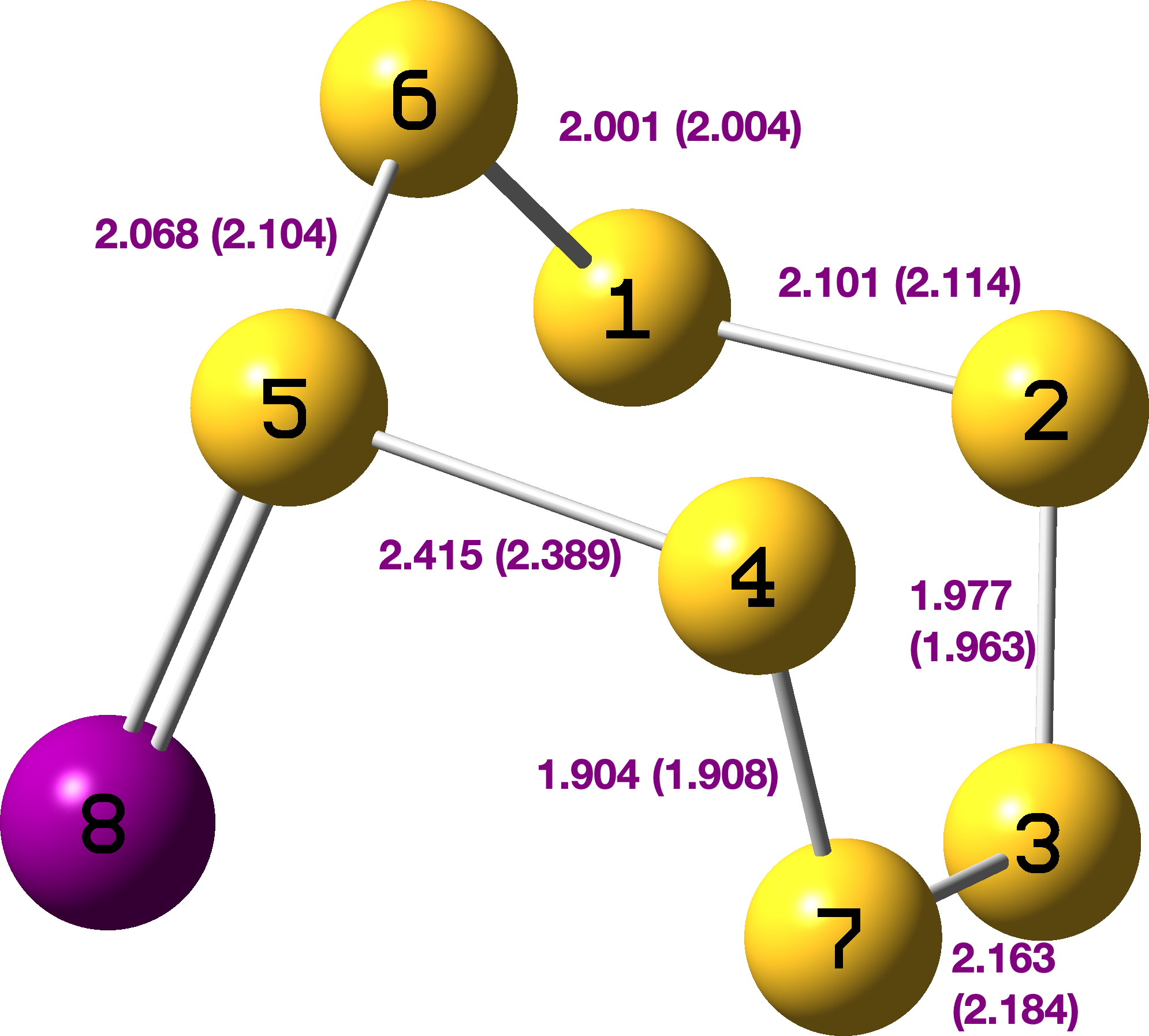
    FAIR data for all the calculations conducted using a dichloromethane continuum solvent are summarised here, [cite]10.14469/hpc/15204[/cite] with individual calculations indicated as a reference to a FAIR repository dataset  (Table A1). The computed geometry of TS1 changes from the initial values of a) the new S7-S8 bond 2.195 → 2.356Å, b) S8-Cl 2.918 → 2.616Å and c) S7-Ti 2.572 → 2.562Å (Table 2, atom numbering shown in  Figure 1).

    Scheme 3.  Revised reaction scheme showing the formation of the ion-pair Int0 rather than Int1 computed using geometries optimised with continuum solvation effects included.

    Table 2. Calculated geometries for TS1 – Ts4 with solvation
    # Geometry # Geometry
    TS1 Int0
    TS2 Int2
    TS3 TS4

    When same potential energy surface is computed with a continuum solvent model (Table 3), the “hidden intermediate” present for the gas phase model in the original IRC profile of TS1 (Table 1) now becomes a real ion-pair intermediate (labelled here Int0 in  scheme 3 to distinguish it from Int1 in scheme 2) with a discrete chloride anion. Thus Int0 occurs at an IRC value of ~3.5 in the plots below, although it has a very small exit barrier via a transition state, here labelled TS2 (different from the TS2 labelled in scheme 2 above). The plots below  (Table 3) are the result of concatenating two separate IRC plots for TS1 and TS2.

    Table 3. IRCs for TS1 + TS2 in a continuum solvent model

    The gas phase (left) and continuum solvent (right) IRCs are summarised below (Figure 2) to enable a visual comparison of the two potential energy surfaces.

    Figure 2. A comparison of the computed IRC energy profiles in the gas phase (left) and continuum dichloromethane solvent (right).

    This indicates a change from Mechanism IV under gas phase conditions (scheme 2) to one closer to mechanism II with continuum solvent; an SN2 like displacement of chloride ion at sulfur, followed in a second step by Cl…Ti bond formation and Ti…S cleavage, Scheme 3. This can also be summarised by the following plots of bond lengths in Figure 3.

    Figure 3. Selected bond length variation for the concatenated IRC profile for TS1 + TS2 in a continuum solvent. See Figure 1 for atom numberings.

    The overall results can be summarised in Table 4 indicting that both the original r2scan-3c/Def2-mTZVPP and the MN15L functional used here are both in reasonable agreement with the experimental results obtained from kinetic studies. Also noteworthy is that for substituents such as e.g. 2b, the enthalpy of activation may actually be negative, with the resulting positive value for the free energy of activation being a consequence of a very negative entropy of activation.

    Table 4. Solvent DCM model: Mechanism II through to Ion-Pair intermediate Int0 rather than the original Int1.
    Source ΔH ΔS ΔG
    1a: Article 6.0 -45.7 19.6
    1a: This work 3.4 -31.5 12.8
    1a: Expt/1M 0.0 -49.7 14.8
    2a: Article 1.7 -45.7 15.3
    2a: This work 0.8 -39.5 12.6
    2a: Expt/1M -2.3 -48.2 12.6
    2b: Article ~10.8
    2b: This work -1.4 -34.1 8.80
    6m: Article ~25.0
    6m: This work 8.95 -39.2 20.6

    Conclusions

    The overall conclusion is simple; when the possibility of ion-pair formation on a reaction potential energy surface is present, it matters how the geometries of all the species involved are obtained. A gas phase geometry optimised model is likely to disfavour the formation of such an ion-pair, whereas a continuum solvent geometry optimised model is more likely to promote such species. This effect can be seen especially in Figure 2, where the two potentials are shown side by side. Such promotion of ion-pairs is likely to reduce any concerted behaviour of the reaction into a two-stage stepwise process. Thus the concerted nature of mechanism IV (Scheme 1) morphs into more stepwise behaviour (Mechanism II, Scheme 1 modified as in Scheme 3). Overall however, while the resulting calculated energetic barriers, although reduced by inclusion of solvation, are unlikely provide definitive evidence of which mechanism actually prevails, the greater change in dipole moment in the stepwise behaviour is more consistent with the experimentally observed effects of solvent identity on the rate.


    Appendix

    All energies for the computed species, obtained with optimisation with a dichloromethane continuum solvent model. Values for the default concentration of 0.0409M are shown for completeness and to enable facile reconciliation with those included in the published FAIR datasets.

    Table A1. Calculations at the MN15L/Def2-TZVPP; Def2-QZVPP on Ti/CPCM=Dichloromethane level with geometry optimisation.
    1a (scheme 2)
    Species h-H T.h-S h-G qh-H T.qh-S qh-G
    Z=S -3227.1212a
    -3227.1212b
    0.05845
    0.05543
    -3227.179639
    [cite]10.14469/hpc/15150[/cite]
    -3227.176621
    -3227.12140
    -3227.12140
    0.05845
    0.05543
    -3227.17985
    -3227.17683
    S2Cl2 -1716.63131a
    -1716.63135b
    0.03637
    0.03335
    -1716.667668
    [cite]10.14469/hpc/15196[/cite]
    -1716.664658
    -1716.63135
    -1716.63135
    0.03637
    0.03335
    -1716.66771
    -1716.66470
    Sum -4943.75254a
    -4943.75254b
    0.09481
    0.08878
    -4943.847307
    -4943.841279
    -4943.75275
    -4943.75275
    0.09481
    0.08878
    -4943.84756
    -4943.84152
    TS1 -4943.74534a
    -4943.74534b
    0.07984
    0.07682
    -4943.825172
    [cite]10.14469/hpc/15179[/cite]
    -4943.822153
    -4943.74734
    -4943.74734
    0.07984
    0.07682
    -4943.82717
    -4943.82415
    ΔTS1 4.52 -31.53 13.88 3.39 -31.52 12.79
    ΔTS1b 4.52 -25.17 12.00 3.39 -25.17 10.90
    Int0c -4943.75128 0.08039 -4943.831670
    [cite]10.14469/hpc/15205[/cite]
    -4943.75298 0.08039 -4943.83337
    ΔInt0 0.76 -30.36 9.81  -0.15 -30.36 8.91
    TS2 -4943.74951 0.07801 -4943.827519
    [cite]10.14469/hpc/15154[/cite]
    -4943.75100 0.07801 -4943.82901
    ΔTS2 1.88 -35.33 12.42 1.10 -35.36 11.64
    Int2 -4943.79255 0.08031 -4943.872859
    [cite]10.14469/hpc/15206[/cite]
    -4943.79432 0.08031 -4943.87463
    ΔInt2 -25.13 -30.53 -16.03 -26.09 -30.53 -16.99 (-11.0 lit)
    TS3 -4943.77886 0.08003 -4943.858887
    [cite]10.14469/hpc/15248[/cite]
    -4943.78065 0.08003 -4943.86068
    ΔTS3 -16.54 -30.12 -7.27 -4943.78065 -8.23
    Int3 -4943.78456  0.079887 -4943.864446
    [cite]10.14469/hpc/15254[/cite]
    -4943.78619 0.079887 -4943.86607
    ΔInt3 -20.12  -31.42 -10.76 -20.98 -31.42 -11.62
    TS4 -4943.78439 0.07807 -4943.862461
    [cite]10.14469/hpc/15251[/cite]
    -4943.78599 0.07807 -4943.86406
    ΔTS4 -20.01 -35.23 -9.51 -20.86 -35.23 -10.36
    S7 as product -2787.10568 0.04667 -2787.152347
    [cite]10.14469/hpc/15578[/cite]
    -2787.10608 0.04667 -2787.15275
    Cp2TiCl2 -2156.70450 0.04990 -2156.754401
    [cite]10.14469/hpc/15579[/cite]
    -2156.70456 0.04990 -2156.75447
    Product P -4943.81017 0.09657 -4,943.906749 -4943.81064 0.09657 -4,943.90722
    ΔProduct P -36.19 3.70 -37.30 -36.33 3.70 -37.43
    (-36.9 lit)
    2a:
    Z=CMe2 -2946.72598a
    -2946.72598b
    0.06683
    0.063808
    -2946.7928059
    [cite]10.14469/hpc/15193[/cite]-2946.789786
    -2946.72674
    -2946.72674
    0.06683
    0.063806
    -2946.79356
    -2946.790542
    S2Cl2 -1716.63131a
    -1716.63135b
    0.03637
    0.03335
    -1716.667668
    [cite]10.14469/hpc/15196[/cite]
    -1716.664658
    -1716.63135
    -1716.63135
    0.03637
    0.03335
    -1716.66771
    -1716.66470
    Sum -4663.35729
    -4663.35729
    0.10319
    0.097158
    -4663.4604739
    -4,663.454444
    -4663.35808
    -4663.35808
    0.10319
    0.097156
    -4663.46127
    -4663.455242
    TS1 -4663.35477a
    -4663.35477b
    0.08445
    0.081429
    -4663.439222
    [cite]10.14469/hpc/15195[/cite]-4663.436203
    -4663.35677
    -4663.35677
    0.08445
    0.081429
    -4663.44122
    -4663.438201
    ΔTS1a 1.58 -39.45 13.34 0.82 -39.46 12.59
    ΔTS1b 1.58 -33.10 11.45 -33.10 10.69
    TS2 -4663.36425 0.08207 -4663.446325
    [cite]10.14469/hpc/15194[/cite]
    -4663.36574 0.08207 -4663.44782
    ΔTS2 -4.37 -44.44 8.88 -4.80 -44.44 8.44
    2b:
    Z=C(NMe2)2 -3135.79512
    -3135.79512
    0.07575

    0.072730

    -3135.870870
    [cite]10.14469/hpc/15197[/cite]-3135.867852
    -3135.79611
    -3135.79611
     0.07575
    0.072730
    -3135.87186
    -3135.86884
    S2Cl2 -1716.63131a
    -1716.63135b
    0.03637
    0.03335
    -1716.667668
    [cite]10.14469/hpc/15196[/cite]
    -1716.664658
    -1716.63135
    -1716.63135
    0.03637
    0.03335
    -1716.66771
    -1716.66470
    Sum -4852.4264
    -4852.4264
    0.11212
    0.10608
    -4852.538538
    -4852.53251
    -4852.42745
    -4852.42745
    0.11212
    0.10608
    -4852.5396
    -4852.53354
    TS1 -4852.42719
    -4852.42719
    0.09602
    0.09300
    -4852.523215
    [cite]10.14469/hpc/15199[/cite]
    -4852.520196
    -4852.42964
    -4852.42964
    0.09591
    0.09289
    -4852.52555
    -4852.522536
    ΔTS1a -0.49 -33.86 9.62 -1.37 -34.11 8.80
    ΔTS1b -0.49 -27.53 7.27 -1.37 -27.76 6.91
    TS2 -4852.43669 0.09143 -4852.528126
    [cite]10.14469/hpc/15198[/cite]
    -4852.43823 0.09143 -4852.52966
    ΔTS2 -6.44 -43.54 6.53 -6.76 -43.54 6.22
    6m:
    Z=C(CN)2 -3052.59951
    -3052.59951
    0.06956
    0.06654
    -3052.669074
    [cite]10.14469/hpc/15200[/cite]
    -3052.666055
    -3052.60050
    -3052.60050
    0.06956
    0.06654
    -3052.67007
    -3052.66705
    S2Cl2 -1716.63131a
    -1716.63135b
    0.03637
    0.03335
    -1716.667668
    [cite]10.14469/hpc/15196[/cite]
    -1716.664658
    -1716.63135
    -1716.63135
    0.03637
    0.03335
    -1716.66771
    -1716.66470
    Sum -4769.23082
    -4769.23082
    0.10593
    0.09989
    -4769.336742
    -4769.330713
    -4769.23185
    -4769.23185
    0.10593
    0.09989
    -4769.3378
    -4769.33175
    TS1 -4769.21540a
    -4769.21540b
    0.08731
    0.08423
    -4769.30271
    [cite]10.14469/hpc/15203[/cite]
    -4769.29970
    -4769.21759
    -4769.21759
    0.08731
    0.08423
    -4769.30490
    -4769.30188
    ΔTS1a 9.68 -39.18 21.36 8.95 -39.18 20.63
    ΔTSb 9.68 -32.83 19.46 8.95 -32.83 18.74
    TS2 -4769.22451 0.08582 -4769.310328
    [cite]10.14469/hpc/15201[/cite]
    -4769.22626 0.08582 -4769.31208
    ΔTS2 3.96 -42.32 16.58 3.51 -42.32 16.13

    a0.0409M b1.0M cInt0 is ion pair comprising S+ and Cl See Table 3 and scheme 3.


    Footnotes

    ‡Currently at least, Gaussian is better supported by associated visualisation programs then ORCA.


    This post has DOI: 10.59350/1a48f-rj714

  • Reinvestigating the reported transition state structure of a concerted triple H-tunneling mechanism.

    Substituting a deuterium isotope (2H) for a normal protium hydrogen isotope can slow the rate of a chemical reaction if this atom is involved in the reaction mode. The magnitude of the effect, referred to as a kinetic isotope effect or KIE is normally 2-7, but higher values of 20 or even more♥ are sometimes observed due to a phenomenon known as proton tunnelling. So a recent report[cite]10.1021/acscentsci.5c00943[/cite] of a 1H/2H of ~2440 for the following palladium catalysed reaction caught my eye:

    When the protium in the solvent methanol and the hydrogen gas were replaced by deuterium, the rate of the reaction slowed by ~2400. This immediately begs one question: what was the % of deuterium incorporated into the 2H2 and MeOD? It would have to be >99.994% to eliminate any contribution from the presumably faster reacting 1H isotope, and this level of deuteriation is some ask! Leaving this issue aside, the authors then carried out some DFT modelling to come up with a proposed mechanism (below), which they refer to as a concerted triple hydrogen transfer reaction (the curly arrows by the way are mine; arrows are shown in the graphical abstract for this article but they are likely not curly electron arrows but simply schematic). The large value of the KIE was then attributed in part to a novel form of triple hydrogen tunnelling.

    My second reality check was to search the crystal structure database for instances of the proposed catalyst containing a Pd-H substructure. Nine examples of compounds with such Pd-H bonds emerge, but none have the H-Pd(OR)3 motif shown above, which is likely to be a transient catalytic species rather than a stable isolable one. This species (FOTBAR)[cite]10.1021/ic00306a034[/cite] with one OPh and two P ligands on the Pd is the closest match; although the trans relationship of the Pd-H and Pd-O bonds might preclude it functioning as a catalyst according to the mechanism above.

    My next check related to the DFT procedure used, which was reported as B3LYP with apparently a 6-311+G(d,p) basis set, but no dispersion correction added. We had previously observed[cite]10.1002/adsc.202400909[/cite] that functionals such as B3LYP are not particularly well suited for transition metal modelling, preferring a newer variety such as MN15L.[cite]10.1021/acs.jctc.5b01082[/cite]

    Finally, we also recollected our experience in modelling KIE effects using relatively modest basis sets such as 6-31G(d,p) and 6-311+G(d,p)[cite]10.1039/D3DD00246B[/cite] where we showed that the calculated KIE were inaccurate. Basis sets of eg Def-TZVPP or better were found to be essential. So here I test this hypothesis for a small selection of functional and basis sets as an initial exploration.

    The calculations are published here (Table below).[cite]10.14469/hpc/15569[/cite] Row 1 shows the values given in the article,[cite]10.1021/acscentsci.5c00943[/cite] and for which a free energy of activation of 27.0 kcal/mol was indicated. Attempting to replicate this here, the main article declares that a 6-31G* basis set was adopted for the H, C, and O atoms… and the LANL2DZ basis set was adopted for Pd atoms. The supporting information records this instead as 6-311+G(d,p) for these atoms (Table S5. — B3LYP/6-311+G(d,p)/Lanl2dz level) which was used here. The basis used for Ti was not noted in either article or ESI; here it was set to 6-31G(d,p).[cite]10.1021/acs.jcim.9b00725[/cite] Using the Gaussian 16 program, my calculation gave the results shown in row 2, with geometry optimisation starting from the coordinates given in the ESI, giving a final RMS force of 0.000008 au – this value is not available for comparison with the original article, nor is the final total energy of the system. The imaginary transition state mode is 940 cm-1 compared to the reported value of 1306 cm-1, a not insignificant difference and which may arise from the reported basis set uncertainty. The bond lengths also differ somewhat, but the angle subtended at the Pd-H-C system is more or less linear. The newly computed free energy of activation is significantly lower. Re-modelling, but now including the effects of a methanol solvent also induces some significant changes in the geometry, but only a small change in the imaginary mode to 979 cm-1 (entry 3).

    Changing the functional from B3LYP to MN15L (entry 4) significantly reduces the imaginary mode value and here the effect of improving the basis set quality (entry 5) is large, reducing the imaginary transition state mode to 497 cm-1 Entry 6 shows the values for the r2scan-3c functional discussed in an earlier post,[cite]10.59350/bc8j8-dtj11[/cite] revealing a transition state mode similar to the others. The free energy barriers range from 27.0 kcal/mol quoted in the article[cite]10.1021/acscentsci.5c00943[/cite] down to 18.3 (entry 3) with the r2scan-3c functional being rather higher. Given that this reaction proceeds at temperatures of 253 – 298K, one might expect a barrier closer to the lower end of this range rather than the reported computed value of 27.0 kcal/mol and in this regard, the value for the r2scan-3c functional seems quite reasonable.

    The transition state mode vibrational vectors are quite similar (entries 3 and 6 shown respectively below), indicating that the PD-H-C and adjacent O-H-O contributions are quite similar, whilst the final third transfer has a smaller contribution. This shows that the three transfers are not exactly synchronous, and hence any tunnelling contributions for the three transfers are unlikely to be the same.

    row Method rPd-H rH-C rO1-H, Å rH-O2 rH-O2 rH-O3 α Pd-H-C, ° νi ΔG
    1 B3LYP/6-311+G(d,p)/Lanl2dz
    gas phase†
    1.694 1.297 1.269 1.158 1.153 1.273 166.1 1306 27.0
    2 B3LYP/6-311+G(d,p)/Lanl2dz
    gas phase‡[cite]10.14469/hpc/15570[/cite],[cite]10.14469/hpc/15572[/cite]
    1.677 1.303 1.258 1.151 1.141 1.278 177.1 940 18.6
    3 B3LYP/6-311+G(d,p)/Lanl2dz/

    SCRF=methanol[cite]10.14469/hpc/15574[/cite],[cite]10.14469/hpc/15575[/cite]
    1.736 1.241 1.295 1.132 1.181 1.229 177.2 979 18.3
    4 MN15L/6-311+G(d,p)/Lanl2dz/

    SCRF=methanol[cite]10.14469/hpc/15589[/cite],[cite]10.14469/hpc/15575[/cite]
    1.703 1.283 1.360 1.096 1.082 1.383 143.8 497 25.8
    5 MN15L/Def2-TZVPP/
    SCRF=methanol
    1.633 1.363 1.306 1.120 1.073 1.405 151.3 935 28.0
    6 r2scan-3c/Def2-mTZVPP/

    SCRF=methanol
    1.639 1.360 1.212 1.199 1.129 1.290 136.7 985 21.3

    Before a transition state model can be used to infer the KIE for isotopic substitution, it has to be tested against e.g. crystal structures and variation in more accurate basis sets and density functionals. The geometry of the transition state should also be optimised to high accuracy. Whether the KIE reported (~2440) would survive modelling at these more accurate levels remains to be seen. Or indeed whether such an exceptionally high value is directly related to the synchrony of the three hydrogen transfer shown above (“triple hydrogen tunneling”).

    ♥The largest value I know of that has been claimed for a KIE is the phenomenal value of ~1016[cite]https://doi.org/10.1016/j.proeng.2017.03.024[/cite] †[cite]10.1021/acscentsci.5c00943[/cite] SI Table S7 etc.

  • The mechanism of borohydride reductions. Part 2: 4-t-butyl-cyclohexanone – Dispersion induced stereochemistry.

    Part one of this topic was posted more than ten years ago.[cite]10.59350/aqrgh-jw887[/cite] I clearly forgot about it, so belatedly, here is part 2 – dealing with the stereochemistry of the reduction of tert-butyl-cyclohexanone by borohydride in water. The known stereochemistry is nicely summarised in this article, along with an extensive  history of possible explanations of the reasons for the stereochemical preference.[cite]10.1080/10610270701268815[/cite] Put simply, the hydride nucleophile attacks the carbonyl from an axial rather than equation direction with a ratio of 10:1 (ΔΔG 1.37 kcal/mol). So does the model I previously proposed[cite]10.59350/aqrgh-jw887[/cite] support this and give any indication of why the stereochemistry is axial?

    The calculated transition states are shown below (click on image to get interactive 3D model). Note also the unusual calculated B-H…H-O hydrogen bonded distances of ~1.8Ã…. A search of the CSD (crystal structure database) reveals surprisingly few such examples, but one interesting one is as short as ~1.73Ã…[cite]10.1021/ja982959g[/cite]

    DFT calculations were conducted using Gaussian 16 at the B3LYP/Def2-TZVPP/SCRF=water level[cite]10.14469/hpc/15559[/cite] for transition state location and energies (including D3+BJ dispersion) and using ORCA 6.1[cite]10.1002/wcms.70019[/cite] for calculating D4 dispersion energies.[cite]10.1039/D0CP00502A[/cite]

    Lithium Borohydride

    Sodium borohydride

    As well as computing the free energy difference ΔΔG‡ between the two transition states, I also looked at the total dispersion energy contributions to these energies at the third generation D3+BJ and the fourth generation D4 levels, shown below as the difference between the axial and equatorial transition states.

    Counter ion ΔD3 dispersion ΔD4 dispersion ΔG‡axial ΔG‡equatorial ΔΔGh†
    Lithium borohydride 1.15 0.932 12.13 12.93 0.80
    Sodium borohydride 1.22 0.745 13.31 14.16 0.85

    †Harmonic energies.

    The calculations reveal that using either Li or K as the counterion to borohydride, the axial transition state is lower in energy than the equatorial, by around 0.85 to 0.80 kcal/mol in total free energy. These values correspond to an axial/equatorial ratio of around  3.9-4.2:1, a little bit lower than observed experimental value of 10:1.[cite]10.1080/10610270701268815[/cite] The D3+BJ and D4 dispersion energies follow the same trend, with the suggestion that the Li ion is slightly more stereoselective than the Na ion, perhaps due to the more compact nature of the transition state.

    So we might conclude that the stereochemical preference for axial hydride delivery to tert-butyl-cyclohexanone could be explained entirely by the differing dispersion energy contributions of the two transition states. This in one way is a deeply unsatisfactory explanation, since the dispersion energy difference is the total sum of many individual dispersion contributions and is largely unpredictable until calculated. Chemists like simple rules and this is not apparently amenable to such a simple rule. Indeed perhaps the rule should simply be to always compare the computed dispersion energies of two (or more) isomeric transition states before seeking other explanations!


    A source of error in the calculated free energies could be the treatment of the vibrational modes as harmonic. A quasi-harmonic treatment is available[cite]10.12688/f1000research.22758.1[/cite] which should give a more reliable estimate of the relative free energy. Using this approach (for settings see [cite]10.14469/hpc/15565[/cite]) ones gets the values below. Although the discrimination is slightly reduced, the overall prediction of axial hydride attack is still confirmed.

    system> hG qhG
    LiBH4 ax -884.325907 -884.328233 (ΔΔG -0.62)
    LiBH4 eq -884.324625 -884.327246
    NaBH4 ax -1039.096789 -1039.100009 (ΔΔG -0.78)
    NaBH4 eq -1039.095445 -1039.098771
  • Why an Electron-Withdrawing Group is an o, m-Director rather than m-Director in Electrophilic Aromatic Substitution: The example of CN vs NC.

    In the previous post[cite]10.59350/rzepa.28993[/cite] I followed up on an article published on the theme “Physical Organic Chemistry: Never Out of Style“.[cite]10.1021/acs.joc.5c00426[/cite] Paul Rablen presented the case that the amount of o (ortho) product in electrophilic substitution of a phenyl ring bearing an EWG (electron withdrawing group) is often large enough to merit changing the long held rule-of-thumb for EWGs from being just meta directors into being ortho and meta-directors, with a preference for meta. I showed how Paul’s elegant insight could be complemented by an NBO7 analysis of the donor-acceptor interactions in the σ-complex formed by protonating the phenyl ring bearing the EWG. Both the o– and m– isomers showed similar NBO orbital patterns and associated E(2) donor/acceptor interaction energies and also matched the observation that the proportion of meta is modestly greater than ortho substitution (steric effects not modelled). These interactions were both very different from those calculated for the para isomer.

    Here using the same NBO7 analysis, I look at what happens when you transpose the atoms of CN to form the isocyanide NC.

    The orbital overlaps for NC as substituent can be seen as 3D rotatable models below (click on image to open model).

    These effects (ωB97XD/Def2-QZVPP/SCRF=DCM) can be summarised in the table below.

    ΔΔG, kcal/mol o m p
    CN 0.51 0.0 1.23
    NC 0.36 2.86 0.0
    NBO7 E(2) Terms: o m p
    CN as donor 14.3 9.4 0.2
    CN as acceptor 18.8 23.9 0.2
    NC as donor 28.8 17.9 0.4
    NC as acceptor 12.4 15.7

    What emerges is that the two groups cyanide (CN) and isocyanide (NC) can act as both π-electron acceptors and π-electron donors. For the former, the o– and m– electron acceptor interactions are larger, whilst for the latter the o– and m– electron donor effects dominate. However, the interactions for both o– and m– are qualitatively very similar and it is therefore correct to group them together, as was implied in the title of the recently published article.[cite]10.1021/acs.joc.5c00426[/cite] In contrast it seems appropriate to treat p– direction as a qualitatively different effect.


    This post has DOI: [cite]10.59350/rzepa.29121[/cite]

  • “Typical Electron-Withdrawing Groups Are o, m-Directors Rather than m-Directors in Electrophilic Aromatic Substitution”

    The title of this post comes from an article published in a special virtual issue on the theme “Physical Organic Chemistry: Never Out of Style“[cite]10.1021/acs.joc.5c00426[/cite] There, Paul Rablen presents the case that the amount of o (ortho) product in electrophilic substitution of a phenyl ring bearing an EWG (electron withdrawing group) is often large enough to merit changing the long held rule-of-thumb for EWGs from being just meta directors into these substituents are best understood as ortho, meta-directors, with a preference for meta. I cannot help but add here a citation[cite]10.1039/CT8875100258[/cite] to the earliest publication I can find showing tables of both o,p and m-directing groups and dating from 1887, so this rule is 138 years old (at least).

    Here I thought I might show some computational models (ωB97XD/Def2-QZVPP/SCRF=Dichloromethane)[cite]10.14469/hpc/15341[/cite] derived from the relative stability of the Wheland or σ-complex produced by protonating the Ph-EWG molecule in the three possible positions on the ring – and now taking the opportunity to add some unusual EWGs to the table to explore how far this effect might be pushed.

    I start by looking at the results reported for benzonitrile (EWG = CN), for typical product distributions:

    1. o– (~16%), m– (~82%) and p– (~2%) are cited for nitronium ion as electrophile
    2. o– (23%), m– ( 74%) and p– (3% ) for chlorination
    3. o– (34%), m– (55%) and p– (1%) for uncatalysed bromination (see [cite]10.1002/jcc.23985[/cite] for an unexpectedly complex mechanism and kinetic analysis of this particular reaction)
    4. σ-complex calculations [cite]10.1002/poc.4457[/cite] which result in values of o– (43%), m– (55%) and p– (2%) for benzonitrile.
      • The observation was made[cite]10.1002/poc.4457[/cite] that inclusion of a solvation correction substantially improved the agreement with the limited experimental information available to us regarding product distributions in EAS and the results below certainly confirm that (especially for benzonitrile). Solvent also has a significant effect on the optimised geometry of each system (see Table).

    The calculations reported here[cite]10.14469/hpc/15341[/cite] are similar to those reported using a slightly different model[cite]10.1002/poc.4457[/cite]. For the specific example of benzonitrile, the authors of the original report expressed surprise that their computations showed that “the ortho and meta σ-complexes were … about equally stable“. The results for this blog show a slightly larger and perhaps more realistic (?) discrimination in favour of meta by 0.51 kcal/mol in the free energy.

    Other noteworthy observations include that

    1. compared with CN, the iso-electronic isonitrile group NC is a strong and conventional o/p director, with a preference for p.
    2. The EWG R=BO (a known, albeit very unstable molecule[cite]10.1021/jo401942z[/cite]) is the next isoelectronic isomer of CN and it now reveals a very strong preference for meta-substitution, with only 3.5% ortho. So this group does NOT follow the proposed new rule of “ortho, meta-directors, with a preference for meta” although this is unlikely to ever be able to be tested experimentally due to the instability of this species (it readily trimerises).
    3. Finally in this isoelectronic progression for R=BeF, the calculations seem now to show that this is a strong o– director (61%) and that m is only 29%, again not following the newly modified rule but probably untestable.
    4. R=NO however does seem to be an example of the new modified rule, since the percentage of o– is as high as 23.8%. Here it is significant that for both the o– and mσ-complexes, the NO group was calculated as being co-planar with the phenyl ring, thus indicating significant conjugation – but the p-isomer (2.3%) was twisted and hence un-conjugated (dihedral values shown below).
    5. The same result is obtained for R=NO2, with the p-isomer having a twist angle of 67°.

    Cationic intermediates in electrophilic substitution of Ph-R
    R ΔΔG298, kcal/mol
    (pop, %) ortho,
    rC-R
    Ã…
    ΔΔG298,
    (pop, %) meta
    rC-R ΔΔG298,
    (pop, %) para
    rC-R
    NC, gas
    -4.72
    (21.42)
    1.349
    0.0
    (0.01)
    1.369
    -5.51
    (78.57)
    1.348
    NC, DCM
    -2.50
    (35.51)
    1.359
    0.0
    (0.56)
    1.377
    -2.86
    (63.93)
    1.359
    CN, gas
    -1.38
    (60.56)
    1.423
    0.0
    (6.07)
    1.433
    +0.36
    (33.37)
    1.425
    CN, DCM
    +0.51
    (27.68)
    1.428
    0.0
    (64.05)
    1.435
    +1.23
    (8.27)
    1.433
    BO, gas
    +0.96
    (16.76)
    1.541
    0.0
    (82.34)
    1.540
    +2.72
    (0.09)
    1.549
    BO, DCM
    +1.99
    (3.52)
    1.537
    0.0
    (96.34)
    1.532
    +3.93
    (0.14)
    1.547
    BeF, gas
    +0.23
    (38.78)
    1.727
    0.0
    (56.73)
    1.714
    +1.53
    (4.49)
    1.737
    BeF, DCM
    -0.46
    (61.21)
    1.748
    0.0
    (28.66)
    1.731
    +0.63
    (10.13)
    1.762

    CF3, gas
    +0.25
    (30.86)
    1.524
    0.0
    (46.87)
    1.521
    +0.45
    (22.27)
    1.533
    CF3, DCM
    +1.45
    (8.11)
    1.518
    0.0
    (89.66)
    1.513
    +2.22
    (2.23)
    1.528
    NO, gas
    +0.44
    (25.07)
    1.460
    0.0
    (52.32)
    1.477
    +0.51
    .22.61)
    1.395
    NO, DCM
    +0.68
    (23.84)
    1.458
    0.0
    (73.87)
    1.456
    +2.09
    (2.29)
    1.429
    NO2, gas
    +1.08
    (13.38)
    1.487
    0.0
    (79.88)
    1.487
    +1.49
    (6.73)
    1.476
    NO2, DCM
    +1.80
    (4.73)
    1.480
    0.0
    (94.25)
    1.478
    +2.73
    (1.01)
    1.481

    On to the suggested explanation,[cite]10.1021/acs.joc.5c00426[/cite] where interaction of the π-electrons from the σ-complex with the π* orbital from the EWG was suggested to be stronger not only for the m-isomer but also the o-isomer as compared to the p-isomer. This can now be quantified using NBO7 analysis, which indicates the energy of interaction between pairs of filled donor and empty acceptor orbitals.

    For the m-isomer[cite]10.14469/hpc/15354[/cite] of protonated benzonitrile, the overlap of the two orbitals (CN acting as an acceptor and the phenyl ring as a donor) is shown below (click on the image to get a rotatable 3D model) with blue positively overlapping with purple and red with orange. The NBO E(2) interaction energy is 23.85 kcal/mol (green bond above interacting with R=CN π*).

    A reverse donation, from the π-system of the CN group now acting as a donor to the π* of the benzene ring acting as an acceptor has a smaller E(2) = 9.4kcal/mol. This shows that CN can act as both a donor and as an acceptor, but the latter effect is stronger.

    For the o-isomer[cite]10.14469/hpc/15355[/cite] (below), the NBO E(2) interaction energy is somewhat reduced to 18.8 kcal/mol (orange bond above interacting with R=CN π*). but is still considerable and more or less commensurate with the relative free energies of the o– and m-isomers.

    A reverse donation, from the π-system of the CN group now acting as a donor to the π* of the benzene ring acting as an acceptor has a smaller E(2) = 14.3 kcal/mol. This again shows that CN can act as both a donor and as an acceptor with the latter effect the stronger.

    Things are quite different for the p-isomer[cite]10.14469/hpc/15353[/cite]. The equivalent CN-acceptor/phenyl-donor orbitals are shown below; they has no real overlap and the associated value for E(2) of 0.23 kcal/mol (red bond above interacting with R=CN π*) is tiny compared to that for the o- and m– isomers.

    The reverse donation from the π-system of the CN group now acting as a donor to the π* of the benzene ring acting as an acceptor is equally small, E(2) 0.15 kcal/mol.

    Furthermore, the p-isomer NBO E(2) interaction energy for the same atoms as with o– and m– shows two instances of 3.0 kcal/mol (because of the C2v symmetry), also very much reduced from 23.85 or 18.8 kcal/mol.

    Although many other interactions can be found in the NBO analysis, this accounts for by far the largest difference between the o, m, and p isomers. These results also match with the observation made above that for R=NO, the o– and m-isomers are fully coplanar, but for the p-isomer the NO group is twisted by about 90° with respect to the phenyl ring. This is also reflected in the calculated torsional or twisting vibrations of the R group, being 89 cm-1 for m-Nitroso vs 23 cm-1 for o-nitroso and again 55 cm-1 for m-nitro vs 38 cm-1 for o-nitro.

    So this new NBO7 orbital overlap analysis helps to quantify these effects (the reported qualitative analysis[cite]10.1021/acs.joc.5c00426[/cite] was based on molecular orbitals rather than localised NBO orbitals) and confirms that for some EWG groups at least, the o-isomer is almost as favoured as the m-form. Well, an observation that is 138 years old gets new light shone on it!


    This post has DOI: 10.59350/rzepa.28993

  • Mechanism of the dimerisation of Nitrosobenzene.

    I am in the process of revising my annual lecture to first year university students on the topic of “curly arrows”. I like to start my story in 1924, when Robert Robinson published the very first example[cite]10.1002/jctb.5000435208[/cite] as an illustration of why nitrosobenzene undergoes electrophilic bromination in the para position of the benzene ring. I follow this up by showing how “data mining” can be used to see if this supports his assertion. I have used the very latest version of the CSD crystal structure database to update the version originally posted here in 2020.[cite]10.59350/c6thp-wqe69[/cite]

    I then discuss some possible reasons why Robinson might have thought that bromination goes in the para position, including the observation[cite]10.1002/mrc.1260251118[/cite] that nitrosobenzene is in equilibrium with its dimer, and that such a dimer might be expected to more reactive towards electrophiles than the “deactivated” monomer.

    Not part of the main lecture, but held in reserve for any questions at the end, is the following curly arrow pushing for the dimerisation.

    This raises a simple question – do both the red and blue arrows shown below participate at the same time, or do they go sequentially? Time then for some calculation to answer this last question. An ωB97XD/Def2-TZVPP/SCRF=chloroform calculation[cite]10.14469/hpc/15278[/cite] using a closed shell wavefunction (to correspond to two-electron curly arrows) appears to show a smooth reaction profile. The N-N bond length also converges from no bond to a double bond shortly after the transition state (NN = 1.3Å) without anything intermediate (this for the (Z)-stereochemical isomer, not the one shown above and which will be discussed later). The reported activation free energy for this process ΔG198 is 15.7 kcal/mol[cite]10.1002/mrc.1260251118[/cite] whilst the calculated value by this method is 25.5 kcal/mol. Even allowing for a concentration effect (1M) and quasi-harmonic corrections to the free energy, it is still 23.9 kcal/mol.

    In a previous post[cite]10.59350/k4340-t6971[/cite] when an overly large barrier was computed, one reason is that the wavefunction might have “biradical” character and that the appropriate curly arrows might not be the appropriate two electron variety at all, but instead one-electron ones, as shown below.


    The degree of biradical character is given by the spin-expectation operator <S2>, which has a value of 0.0 for no biradical character and 1.0 for a pure biradical. This time the transition state for the dimerisation is calculated to have a value of <S2> = 0.5418 and ΔG198 is now calculated as 21.8 kcal/mol (20.3 with quasi-harmonic corrections).

    The energy and N-N bond length profiles for the reaction coordinate using “one-electron” curly arrows are shown below, the former being around 4 kcal/mol lower than for the two-electron arrows.


    The dihedral at the central C-N-N-C bond shows it almost entirely twisted at the transition state (as might befit a biradical) and then a smooth rotation to co-planarity (as befits a double bond) as the second bond forms.

    Because the system has C2-symmetry and importantly no plane of symmetry, the π and σ electrons are now allowed to mix together and this can be seen in the two (equivalent) orbital overlap models below at the transition state, each nitrogen lone pair managing to overlap constructively (blue with purple, red with orange, click on the diagram to load the orbitals) with the N-O π* orbital of the second nitrosobenzene.

    Why is this simple system better described (energetically) by the use of one-electron arrows rather than two electron ones? A simple explanation might be that the electrons like to move consecutively simply to reduce the electron repulsion that the two-electron model would impose on it (reducing the electron correlation incurred in the process). It’s probably more complicated than this, but it shows a rare example where two-electron arrows are not the most appropriate for describing a chemical reaction.


    Postscript. The 1-electron transition state (<S2> = 0.981) for formation of the trans stereochemical (E) isomer is higher than the cis (Z) by ~4 kcal/mol.


    Roald Hoffmann has alerted me to an important early paper of his describing exactly this phenomenon.[cite]10.1021/ja00709a002[/cite]

  • S7I1+: The largest anomeric effect exhibited by sulfur.

    In this series of posts about the electronic effects in small sulfur rings[cite]10.59350/rzepa.28615[/cite] I have explored increasingly large induced geometric effects. Here is the largest so far, for the compound S7I1+[cite]10.1021/ic50225a048[/cite]


    The calculated geometry[cite]10.14469/hpc/15236[/cite] is shown below, with the crystallographic values in parentheses – the two matching very well.

    The calculated NBO7 stereoelectronic analysis identifies an especially strong donor (S7) interaction with an acceptor S4-S7, the E(2) energy being 36.9 kcal/mol. The Wiberg S4-S5 bond index is 0.512 and the S-S stretching wavenumber is ν 131. The Wiberg index for S4-S7 is 1.4618 and the S-S stretch ν 667 cm-1, matching the shortest bond.

    The electronic overlap is shown below (click on image to view as a 3D model).

    So we end with the current record for an SLp/SSσ* interaction of 36.9 kcal/mol. Who would have thought that small sulfur rings could be such fun!

  • Cycloheptasulfur sulfoxide, S7O – Anomeric effects galore!

    The monosulfoxide of cyclo-heptasulfur was reported along with cycloheptasulfur itself in 1977,[cite]10.1002/anie.197707161[/cite] along with the remarks that “The δ modification of S7 contains bonds of widely differing length: this has never been observed before in an unsubstituted molecule. and “the same effect having also been observed in other sulfur rings (S8O, S7I1+ and S7O).” Here I take a look at the last of these other molecules, the monosulfoxide of S7, as a follow up to the commentary on S7 itself.[cite]10.59350/rzepa.28407[/cite]

    The axial oxygen isomer is calculated as being 3.68 kcal/mol more stable than the equatorial form[cite]10.14469/hpc/15228[/cite] and a comparison of its calculated (MN15L/Def2-TZVPP) and observed structure is shown below. The S-S lengths do indeed vary widely.

    As before, an explanation is provided by analysing the orbitals of the molecule using NBO7. The interactions tabled below are ordered by the largest first. That from the oxygen into the S4-S5 antibonding NBO (28.2 kcal/mol) is the biggest I have observed for an anomeric effect involving an S-S bond. The greatest all-sulfur effect (16.8 kcal/mol) is increased compared to that previously found for S7 itself (12.35 kcal/mol).

    Donor lone Pair Acceptor antibonding NBO E(2), kcal/mol Acceptor bond distance, Å
    O8 S4-S5 28.2 2.28
    O8 S5-S6 20.2 2.15
    S7 S4-S5 16.8 2.28
    S4 S3-S7 14.8 2.18
    S2 S3-S7 12.5 2.18
    S3 S5-S6 10.3 2.15
    O8 S5-S6 9.6 2.15
    S6 S1-S2 9.1 2.10

    E(2) NBO overlaps Click on image to load 3D rotatable model
    28.2

    20.0

    16.8

    14.8

    12.5

    10.3

    9.6

    9.1

    The S-S stretching modes also vary by more than a factor of two; ν4-7 619 cm-1, ν2-3 528 cm-1, ν1-6 548 cm-1, ν3-7 368 cm-1, ν5-6 331 cm-1, ν4-5 287 cm-1.

    It is indeed remarkable that this small molecule can exhibit as many as eight different anomeric interactions, including two unusually large ones and three regular ones. The result is the profusion of different S-S bond lengths originally commented[cite]10.1002/anie.197707161[/cite] on accompanied by the wide variety of S-S stretching modes. Can this record be beaten, either in the number or the magnitude of the effects. The answer is YES, but not for a known molecule. See next post!

  • The “double-headed” curly arrow as used in mechanistic representations.

    The schematic representation of a chemical reaction mechanism is often drawn using a palette of arrows connecting or annotating the various molecular structures involved. These can be selected from a chemical arrows palette, taken for this purpose from the commonly used structure drawing program Chemdraw. Explanations of how to apply the individual arrows are not always easy to find however! Circled in red are the ones to be discussed here, although most carry fascinating and often subtle meanings!‡

    The most common meaning of the double-headed arrow is probably best illustrated by the scheme below, which involves the addition of a nucleophile to a carbonyl compound, forming a presumed “tetrahedral” intermediate, which is then immediately followed by the eviction of a leaving group – the chloride anion in the example below. The two red arrows show an electron pair firstly moving to the oxygen, and then with the reverse arrow 2 back to reform the carbonyl group. This process is called an addition/elimination mechanism. It is therefore tempting to conflate the two steps into one by instead using a double-headed arrow (3, blue), which if nothing else, saves a little bit of time in the drawing – a useful examination technique!

    Of course, the top scheme (red arrows) is a two-step process, involving a discrete (tetrahedral) intermediate and two transition states. The conflated scheme below it (blue arrows)  might imply (or not) a single-step process with a single transition state. Since few people who draw such schemes have any information on whether it is a two-step or a single step process, the actual chemical meaning of the double-headed arrow is left implicitly ambiguous, without implying anything about how many discrete steps are involved. However, it is tempting to conclude that the first red arrow (1) reduces the double bond order of the carbonyl group to a single bond, which might therefore be expected to lengthen and the second red arrow (2) reforms the double bond, thus shortening the bond. The two arrows clearly do not move simultaneously. The conflated third arrow (3) leaves the status of the carbonyl bond length changes undefined, or might it mean that it first gets longer and then shorter along the reaction path, depending of course on which moves first!

    Enter computation, where the energy pathway of such a reaction can be computed, along with geometries at each stage. Here I explore three examples† to see what results (ωB97XD/De2-TZVPP/SCRF=DCM), FAIR DOI: 10.14469/hpc/13171

    Acetyl chloride + Methanol.

    This uses a model in which a proton transfer from the methanol to the chloride anion is facilitated by water. This enables (but does not enforce) a continuous concerted process to occur. This emerges from the computed intrinsic reaction coordinate (IRC) as having a low barrier and an exothermic reaction, which agrees with experimental observation. The required proton transfer is part of the concerted process, albeit occurring in a second lower energy stage (IRC ~+1.5).

    But take a look at how the carbonyl bond length changes along this IRC. It first shortens, and only starts to lengthen as the chloride is evicted. So the carbonyl group actually contracts in length at the transition state, the opposite of what might be inferred by using a double-headed arrow.


    Also included is the dipole moment response, which does seem to correspond to the formation of an ionic intermediate!

    Acetyl chloride + HF.


    Hydrogen fluoride as a nucleophile replacing methanol shows a much higher barrier, since it is less good as a nucleophile in this context.

    Again, observe the bond length response of the carbonyl group, which is at its shortest at the (single step) transition state.

    This corresponds to a different interpretation of the double-headed arrow, as per below, but occuring as part of a single concerted process not involving any intermediate.

    The dipole moment response is rather different from methanol.

    Acetyl chloride + Methylamine.

    The energy profile now shows two distinct transition states (IRC ~7 and again at 0.0). The first is a very low energy addition to the carbonyl group with concerted eviction of the chloride anion, which only hydrogen bonds to the water shown. The second stage is the proton transfer from the nitrogen to the water and thence relayed to the chloride anion, for which a transition state at IRC ~0.0 is found.

    But now observe the bond length response, which shows a distinct maximum around the first transition state (IRC ~7). This is the opposite behaviour to the previous two systems, and now indeed matches the original inferences one might make from the double headed arrow.

    So we can conclude that there are in fact TWO types of double-headed arrow which could be used in mechanistic representations. The first is when arrow 1 is ahead of arrow 2 (red), resulting in initial weakening of the carbonyl bond. The second is when arrow 4 is ahead of arrow 5, resulting in initial strengthening of the carbonyl bond.

    Perhaps to avoid confusion, we really need two different representations of a double-headed arrow to clearly differentiate them! Perhaps a reversal of the direction of the arrowhead? But that does not (yet?) exist in the Chemdraw palette.


    ‡This is part of the arcane “knowledge” of chemistry which is often absorbed rather than learnt by students of the subject, but which as a result becomes a language that becomes inscrutable to anyone else! †Another example was noted in the previous post.

  • Pre-mechanism for the Swern Oxidation: formation of chlorodimethylsulfonium chloride.

    The Swern oxidation[cite]10.1016/0040-4020(78)80197-5[/cite] is a class of “activated” dimethyl sulfoxide (DMSO) reaction in which the active species is a chlorodimethylsulfonium chloride salt. The mechanism of this transformation as shown in e.g. Wikipedia is illustrated below.‡ However, an interesting and important aspect of chemistry is not apparent in this schematic mechanism and to rectify this, a full computed mechanism is laid out below, for which the FAIR data has a DOI: 10.14469/hpc/13151

    The first step involves attack of the oxygen of the DMSO on one carbon of the oxalyl chloride, which can be considered as an addition/elimination‡ substitution at the carbon. The departing chloride anion ends up loosely associated with the sulfur centre. The net result is that the trigonal bipyramidal sulfur is axially coordinated by the chlorine, but equatorially coordinated by the oxygen. The transition state for this step (TS1), shown at IRC = 0.0 in the above energy profile, has a relatively low activation barrier. Click on any animation to view 3D model.

    TS1

    TS1

    The key step is what is called a pseudorotation at the sulfur centre (TS2), which transforms the ax/eq relationship of the Cl/O atoms at the sulfur into an ax/ax one (TS at IRC +8.5 above). This is the energy high point along the reaction path. Note also the large increase in dipole moment, indicating ionic character, along the path involving TS1 and TS2.

    TS2
    TS2

    The S-O bond length response during this transformation is shown below. As the chlorine moves into this di-axial relationship, the S-O bond begins to weaken, from 1.635Ã… at the start, 1.675Ã… at the TS and 2.242Ã… at the end (Def2-TZVPP basis set).

    This prepares the system for the final step (TS3), which is cleavage of the already weakened S-O bond (TS at IRC = 13.0 below, TS = 0.0 being the pseudorotation), accompanied by extrusion of CO, CO2 and Cl. The liberated “ionic” chloride anion ends up loosely associated with the sulfur (2.88Ã…), whilst the “covalent” chlorine which had helped to evict the oxygen is 2.06Ã….


    TS3

    So to conclude, the mechanism of the formation of chlorodimethylsulfonium chloride is perhaps better illustrated as shown below involving the extra pseudorotation step, which as it happens is actually the rate determining step for this reaction. This pre-mechanism to the Swern oxidation is given little attention in most representations, such as the one at Wikipedia. But it actually contains a multitude of interesting (stereoelectronic) effects and is well worth teaching!


    ‡ Well, not quite. The Wiki version does not show the eliminating chloride anion in the first step (which is implied). The resulting curly arrows in the Wikipedia version are unbalanced and hence not formally correct! The double-headed arrow included in the representation above indicates an addition/elimination mechanism, which can be tracked by monitoring the carbonyl C=O bond length (@Def2-TZVPP). It starts at 1.181Å, reaches a maximum of 1.194Å just after the TS and then drops back to 1.186Å at the end as the chloride anion eliminates.


    Citing this blog post: DOI 10.14469/hpc/13156