The substitution of a nucleofuge (a good leaving group) by a nucleophile at a carbon centre occurs with inversion of configuration at the carbon, the mechanism being known by the term SN2 (a story I have also told in this post). Such displacement at silicon famously proceeds by a quite different mechanism, which I here quantify with some calculations.

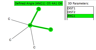
Trialkylsilyl is often used to protect OH groups, and as shown in the diagram above is specifically used to enforce the enol form of a ketone by replacing the OH with OTMS. The TMS can then be removed when required by utilising nucleophilic addition of e.g. fluoride anion from tetra-alkyl ammonium fluoride to form a 5-coordinate silicon intermediate, followed by collapse of this intermediate with expulsion of the oxygen to form an enolate anion. Before starting the calculations, I searched the crystal structure database for examples of R3SIF(OR), as in the search query below.
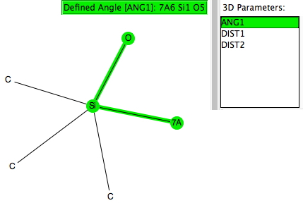
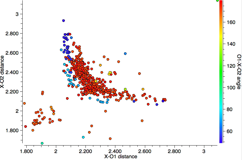
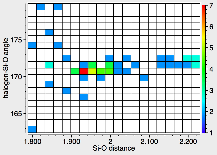
There were 55 instances of such species, and show below are their geometric characteristics. In all cases, the two electronegative substituents occupy the axial positions of a trigonal bipyramidal geometry. This of course is the orientation adopted by the two electronegative substituents in the SN2 mechanism for carbon, but with silicon this carbon "transition state" can be replaced by a stable (and as we see often crystalline) intermediate!
Turning to calculations (ωB97XD/6-31+G(d)/SCRF=thf), one can locate three transition states for the silicon process (there is only one for the SN2 reaction with carbon).
-
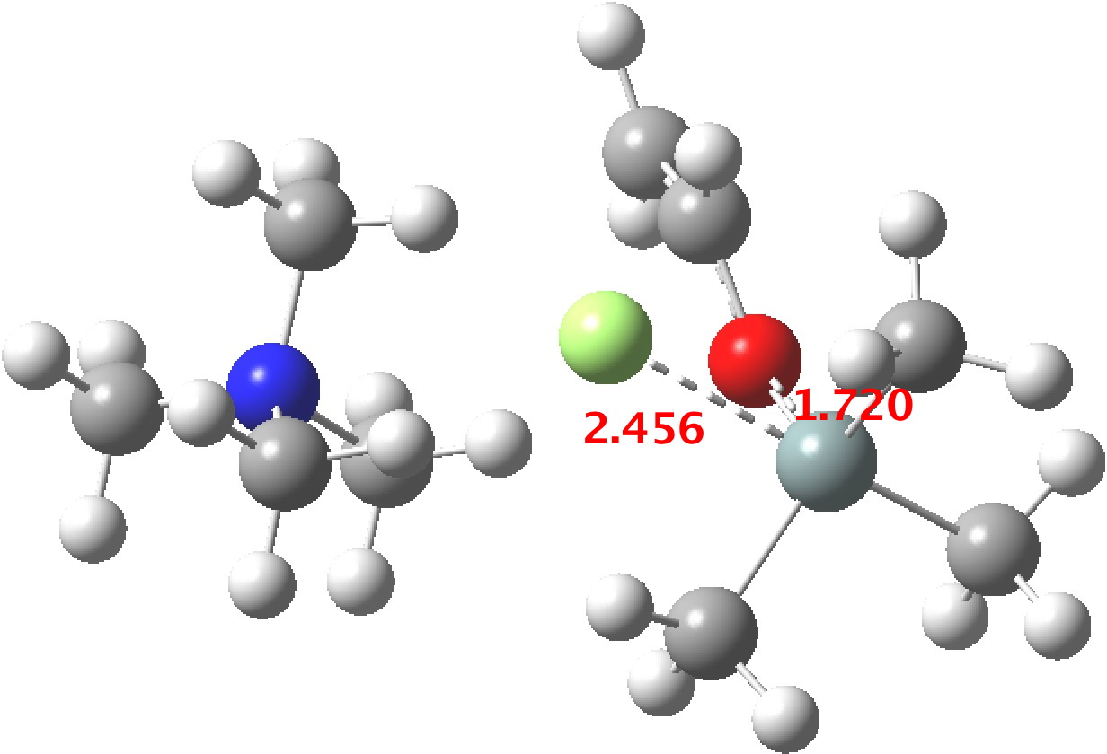
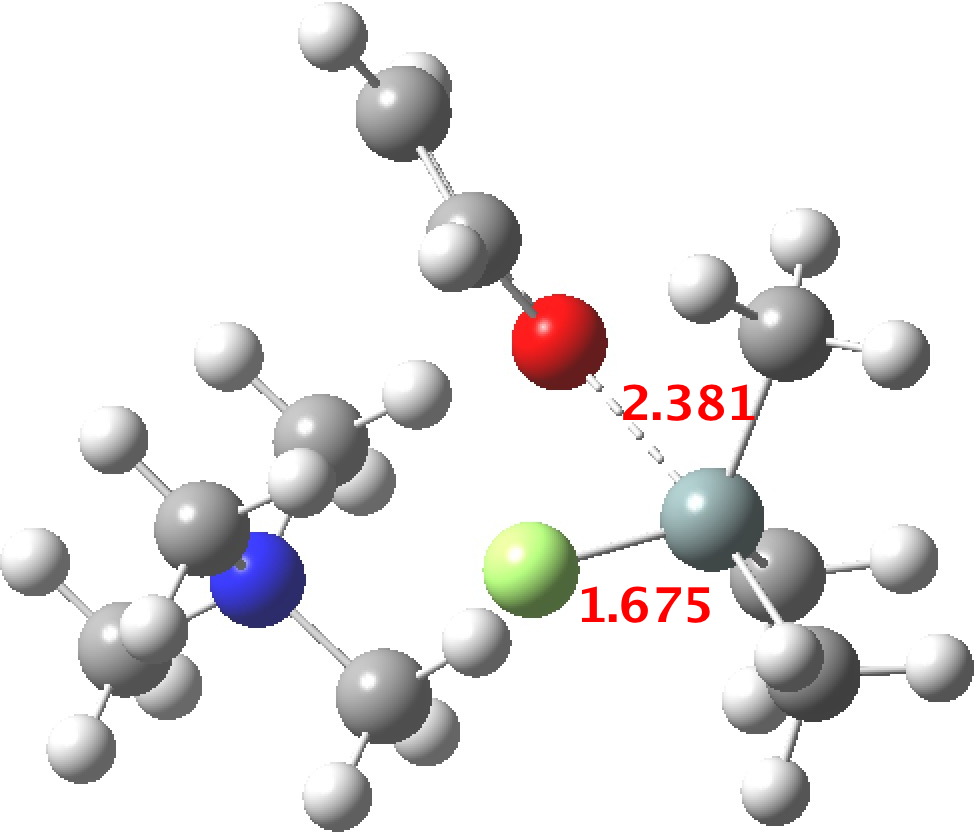
TS1 represents attack of fluoride anion along the axial position of the forming 5-coordinate silicon.[cite]10.14469/hpc/554[/cite],[cite]10.14469/hpc/564[/cite] The oxygen in this instance occupies an equatorial position, and this close proximity between the incoming F(-) and the about to depart OR groups represents a retention of configuration at the Si. Note that the reaction is endo-energic. (c.f. [cite]10.1016/S0040-4020(01)89077-3[/cite]).

-
The next step, TS2[cite]10.14469/hpc/551[/cite],[cite]10.14469/hpc/553[/cite] is to move the F ligand to an equatorial position and the OR group from equatorial to its own axial position so that it can depart in the manner the F adopted to arrive. This requires what is called a Berry pseudorotation, an essentially isoenergic process.

You might note a "hidden intermediate" at IRC ~-7 (the "bump" in the energy profile). This is caused by re-organisation of the ion-pair geometry, with the tetra-alkyl ammonium cation moving its orientation.

-
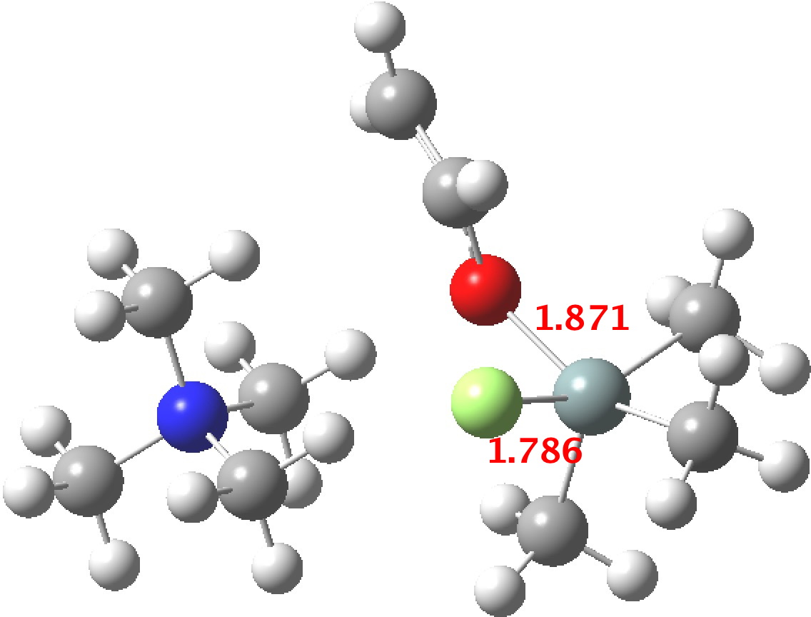
TS3[cite]10.14469/hpc/539[/cite],[cite]10.14469/hpc/552[/cite] now eliminates the –OR group to complete the deprotection.

The free energies are summarised below. Key points include:
-
The overall free energy of deprotection is appropriately exo-energic.
-
The highest energy barrier is actually for pseudo-rotation! This suggests that tuning the deprotection with alternative alkyl or aryl groups on the silicon may be a matter of controlling the Berry pseudorotation process.
-
TS1-3 proceed with the attacking and leaving groups in close proximity (the angle between an axial and an equatorial group is ~90° of course, whereas for a di-axial relationship (the inversion of the SN2 mechanism) it is instead 180°. This close proximity of nucleophile and nucleofuge minimises the required reorganisation of the ammonium counter-ion in the ion-pairs, and possibly also the dipole moments induced by the reactions, the changes of which for the three reactions are shown below:


-
The 5-coordinate intermediate where both F and O are axial is in fact significantly lower in energy (a cooperative effect) than when only one of them is axial, which matches the orientations identified above in the 55 crystal structures. For a substitution to occur, the cooperative strengthening of the Si-O and Si-F bonds must be removed; hence the retention of configuration.
|
System
|
Relative free energy
|
DataDOI
|
|
Reactants
|
0.0
|
[cite]10.14469/hpc/565[/cite]
|
|
TS1
|
7.9
|
[cite]10.14469/hpc/554[/cite]
|
|
Int F(ax), O(eq)
|
5.1
|
[cite]10.14469/hpc/555[/cite]
|
|
TS2
|
10.2 (9.2)*
|
[cite]10.14469/hpc/551[/cite]
|
|
Int F(eq), O(ax)
|
5.1
|
[cite]10.14469/hpc/540[/cite]
|
|
TS3
|
5.2
|
[cite]10.14469/hpc/539[/cite]
|
|
Products
|
-4.0
|
[cite]10.14469/hpc/563[/cite]
|
|
Int F,O(ax)
|
-2.5
|
[cite]10.14469/hpc/550[/cite]
|
*A lower energy orientation of the ion-pair has subsequently been found.[cite]10.14469/hpc/577[/cite]
This analysis shows just how different the carbon and the silicon substitution reactions are and how it is the pseudorotation interconverting two 5-coordinate intermediates that appears to be a key step. But questions remain unanswered. What is the energy of the pseudorotation interconverting an intermediate with ax/eq electronegative groups to one with di-axial electronegative groups? Are there transition states starting from the diaxial intermediate and resulting in elimination, and if so what are their relative energies? I leave answers to a follow up post.